STC Valve Inc Logo Flow Control Valve Stainless Steel Push In Elbow Fitting Stainless Steel Compression Fitting Pneumatic Air Valve Bronze Two Way Process Valve Stainless Steel Manual Ball Valve Stainless Steel Air Actuated Ball Valve Manual Four Way Air Valve Air Filter Regulator Lubricator Combination Air Filter Regulator Lubricator Combination Contact Us
Support & Downloads
Home 1 Push In Fittings 2 Stainless Steel Fittings 3 Compr.&
Barb Fittings
4 Solenoid Valves 5 Process Valves 6 Manual
Ball Valves
7 Actuated Valves 8 Air Valves 9 Air Regulators 10 Air Cylinders Click Here
to Order

Call us at (650) 856-8833 or email us at Sales@StcValve.com.

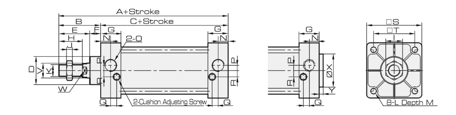
Tie-Rod Air Cylinders Dimensions

All cylinders are build to order at our China factory. Standard Lead Time: 8-10 Weeks; Option for Air Ship: 2-3 Weeks.
There are no returns on cylinders as they are custom made.

The SC/SU series meets ISO6430.

Tie-Rod Cylinders
Model Picture Links Bore Size (mm) Stroke (mm) Magnet (Optional) Options
SC Series Tie-Rod Cylinder Double Acting SC Tie-Rod cylinder Price

Specifications
32
40
50
63
80
100
125
160
200
250
320
25-1000 Standard = without magnet
S = Magnet for Hall Sensor
Mounting Options:
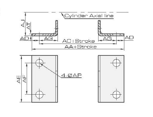
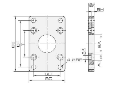
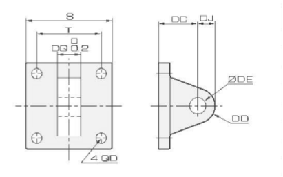
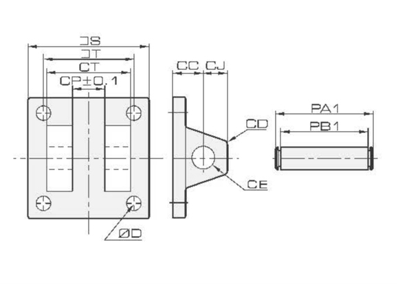
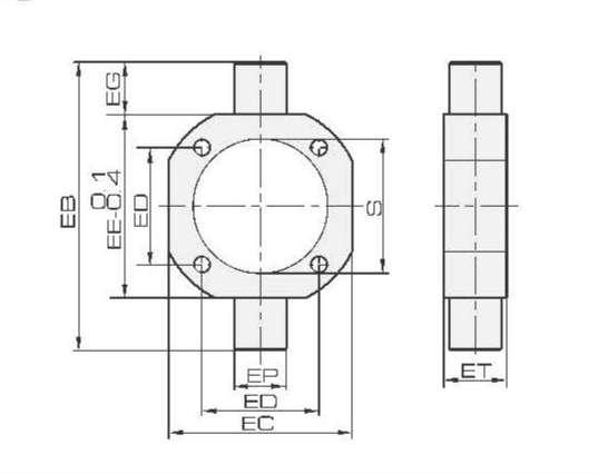
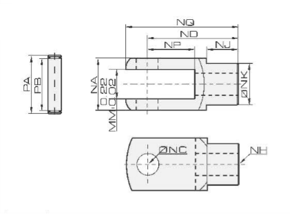
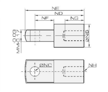
Standard= Standard Mount
LB = Foot Mount
FA = Front Mounting Flange
FB = Back Mounting Flange
CA = Pivot Bracket with Pin
CB = Clevis Bracket with Pin
TCM = Swinging Type Attaching Foot Seat
Y/I = Rod Clevis or Pivot with Pin
SU Series Enclosed Tie-Rod Cylinder Double Acting SU Air Cylinder

Mounting Hardware & Reed Switch
Model LB FA FB CA CB TCM Y I AL-21R-SC SU
Foot Mount Front Mounting Flange Back Mounting Flange Pivot Bracket with Pin Clevis Bracket with Pin Swinging Type Attaching Foot Seat Rod Clevis with Pin Rod Pivot with Pin Reed Switch for SC or SU cylinder
Picture Reed Switch

SC / SU Cylinder Dimensions
Bore/Symbol A A1 B C D E F G H I J K L
32 140 187 182 93 28 32 15 27.5 22 17 6 M10 x 1.25 M6
40 141 191 185 93 32 34 15 27.5 24 17 7 M12 x 1.25 M6
50 150 207 196 93 38 42 15 27.5 32 23 8 M16 x 1.5 M6
63 153 210 199 96 38 42 15 27.5 32 23 8 M16 x 1.5 M8
80 183 258 243 108 47 54 21 33 40 26 10 M20 x 1.5 M10
100 189 264 249 114 47 54 21 33 40 26 10 M20 x 1.5 M10
125 226 330 313 122 55 70 34 33 54 40 10 M27 x 2 M12
160 291 414 377 168 62 93 30 50 72 55 18 M36 x 2 M16
200 347 514 458 180 80 112 55 50 72 55 18 M36 x 2 M16
250 389 578 / 200 90 122 67 54 84 65 21 M42 x 2 M20
320 436 652 / 220 110 126 90 65 96 75 24 M48 x 2 M24
Bore/Stroke M N O P Q R S T V W Z X Y
32 9.5 13.5 G1/8 3.5 7.5 7 45 33 12 10 21 / /
40 9.5 13.5 G1/4 6 8.2 9 50 37 16 14 21 / /
50 9.5 13.5 G1/4 8.5 8.2 9 62 47 20 17 23 / /
63 9.5 13.5 G3/8 7 8.2 8.5 75 56 20 17 23 / /
80 11.5 16.5 G3/8 10 9.5 14 94 70 25 22 29 / /
100 11.5 16.5 G1/2 11 9.5 14 112 84 25 22 29 / /
125 15.5 16.5 G1/2 10 10 11 140 110 32 27 / / /
160 17.5 25 G1/2 / / / 180 140 40 36 / / /
200 17.5 25 G3/4 / / / 220 175 40 36 / / /
250 25 31 G1 18.5 5 40 270 220 50 46 / 90 10
320 28 31 G1 35 15 35 350 270 63 55 / 110 10

LB Foot Mount Dimensions FA/FB Mounting Flange Dimensions
Bore/Symbol AAACADAEAFAGAJAPATBore/SymbolBABBBCBDBEBFBHAJAKBPT
32 153134 9.550 3320.5 2893 32 28.310 4733 7258 6.510.5 6.5733
40 169140 14.557 3623.5 30123 40 32.310 5236 8470 6.510.5 6.5737
50 173149 1268 4728 36.5123 50 38.310 6547 10486 6.510.5 6.5947
63 184158 1280 5631 41123 63 38.312 7656 11698 8.513.5 8.5956
80 200168 1697 7030 49144 80 47.316 9570 143119 10.516.6 10.51270
100 210174 18112 8430 57144 100 47.316 11584 162138 10.516.6 10.51284
125 249249 18140 9045 90167 125 5620 14090 224180 1519 12.516110
160 328288 20180 11560 115188.5 160 6320 180115 280230 2025 16.518140
200 380320 30220 13570 135229 200 8125 220135 320270 2025 16.522175

CA Pivot Bracket with Pin Dimensions CB Clevis Bracket with Pin Dimensions
Bore/Symbol S T DCDDDEDJDQDBore/SymbolCCCDCECJCPCTPAIPBISTD
32 453334141214166.5 32 195121316.332413448336.5
40 503734141414206.5 40 195141320.544534650376.5
50 624734151415206.5 50 193141520.352615462476.5
63 755634151415208.5 63 193141520.352615475568.5
80 9470482020203210.5 80 328202132.3647566947010.5
100 11284482020203210.5 100 328202132.36475661128410.5
125 140110502525257012.5 125 502525257012013612414011012.5
160 180140553030309016.5 160 53030309016018417018014016.5
200 220175603030309016.5 200 603030309016019418022017516.5

TCM Swinging Type Attaching Foot Seat Dimensions
Bore/SymbolEBECEDEEEGEPETS
328753335516163037.5
4011363376325253045.5
5012676477625253055.5
6313888568825253068.5
801641147011425253587.5
10018213284132252540107.5
125210160110160253038134.5
160264200140200323238172.5
200316233175233353246215


Y Rod Clevis with Pin Dimensions

I Rod Pivot with Pin Dimensions
Y/I Rod with Pin Dimensions
Bore/SymbolNANBNCNDNENFNGNHNJNKMMNPNQPAPB
3219201040521520M10 x 1.2515.5161020523021
4024241248672420M12 x 1.2520.5201224623627
5032321664893223M16 x 1.526301632834434
6332321664893223M16 x 1.526301632834434
80404020801124030M20 x 1.530382039.51055242
100404020801124030M20 x 1.530382039.51055242
125624920991225450M27 x 2283830431207566
1607061301251554370M36 x 2405340431539682
2007061301251554370M36 x 2405340431539682

Home Terms of Use Terms of Sale Career Contact Us Click Here to Order
Sizto Tech Corporation © 2001-. All rights reserved. Sizto Tech Corporation © 2001-2016. All rights reserved. Last modified: June 24, 2016.
Information contained herein may be changed without prior notification.