|
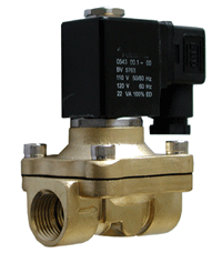
Solenoid Valve Specifications and Dimensions: 3S035 Series
|
Valve Model |
3S035 |
|
Valve Type
|
3 Way Normally Closed (NC) or Normally Open (NO) |
|
Action |
Direct Acting |
|
Cv (Orifice) |
0.5
(3.5mm NC Port, 2.5mm NO Port) |
|
Operating
Pressure (PSI) |
0 to 80
PSI |
|
Operating
Temperature (°C) |
-10 to 120°C
|
|
Port Size (NPT) |
1/4 |
|
Body Materials |
Stainless Steel |
|
Seal Materials:
|
Viton
(Options: EPDM, NBR) |
|
Coil Protection
Insulation Class |
H Class IP65
|
|
Coil Duty
|
100% ED
|
|
Coil Power
|
14W |
|
Electrical
Connections |
DIN |
|
Service |
Air, Gas,
Liquid, Vacuum |
|
2/3 Direct Acting Solenoid Valve Normally Closed (3S035
Series)
As shown
below, when the valve is de-energized (left diagram), the plunger under the
force of spring seals the main orifice, and port CYL connects with port EX.
When the valve is energized (right diagram), the coil magnetic force pulls
back the plunger and closes port EX, and connects port IN to CYL.
To operate the 3S035 as a normally open
diverter , you need to connect the supply air to Port No 1. The Top Port is
the normally open port and Port No. 2 is the normally closed port. In the
configuration, air goes from Port No. 1 to the Top Port when the valve is
de-energized. When it is energized air will go from Port No. 1 to Port No. 2
and the Top Port will be shut off.
To operate the 3S035 as a normally open
on/off valve, you need to connect the supply air to the Top Port. The Port
No.1 is the normally open port. In the configuration, air goes from the Top
Port to Port No. 1 when the valve is de-energized. When it is energized the
Top Port is shut off, and Port No. 1 will be exhausted to Port No. 2. To
operate the 3S035 as a normally open diverter , you need to connect the
supply air to Port No 1. The Top Port is the normally open port and Port No.
2 is the normally closed port. In the configuration, air goes from Port No.
1 to the Top Port when the valve is de-energized. When it is energized air
will go from Port No. 1 to Port No. 2 and the Top Port will be shut off.
  
|
|

|
|
Electrical Coil Connections |
|
For DIN Coil |
To connect DIN coil:
1. Remove the Philip screw from the plastic housing and unplug it from the
DIN coil.
2. From the screw opening, push the terminal block out from the plastic
housing.
3. Note the 1, 2 and ground markings on underside of DIN enclosure.
4. For DC DIN Coil, Connect 1 to Positive, 2 to Negative.
5. For AC DIN Coil, connect 1 to HOT wire, 2 to Neutral wire, and if
required connect ground to ground wire. |
|
For Grommet Coil |
To connect Grommet coil:
1. For DC Coil, connect one of the two wires to Positive, and the
other wire to Negative.
2. For AC Coil, connect one of the two wires to HOT wire, and the other wire
to neutral wire. |
|


