


Call us at (650) 856-8833 or email us at Sales@StcValve.com.
Solenoid Valve Specifications and Dimensions: 2W025-050 Series
|
|
||||||||||||||||||||||||||||||||||||||||||||||||||||||||||||||||||||||||||||||||||||||||||||||||||||||||||||||||||||||||||||||||||||||||||||||||||||||||||||||||||||||||||||||||||||||||||||||
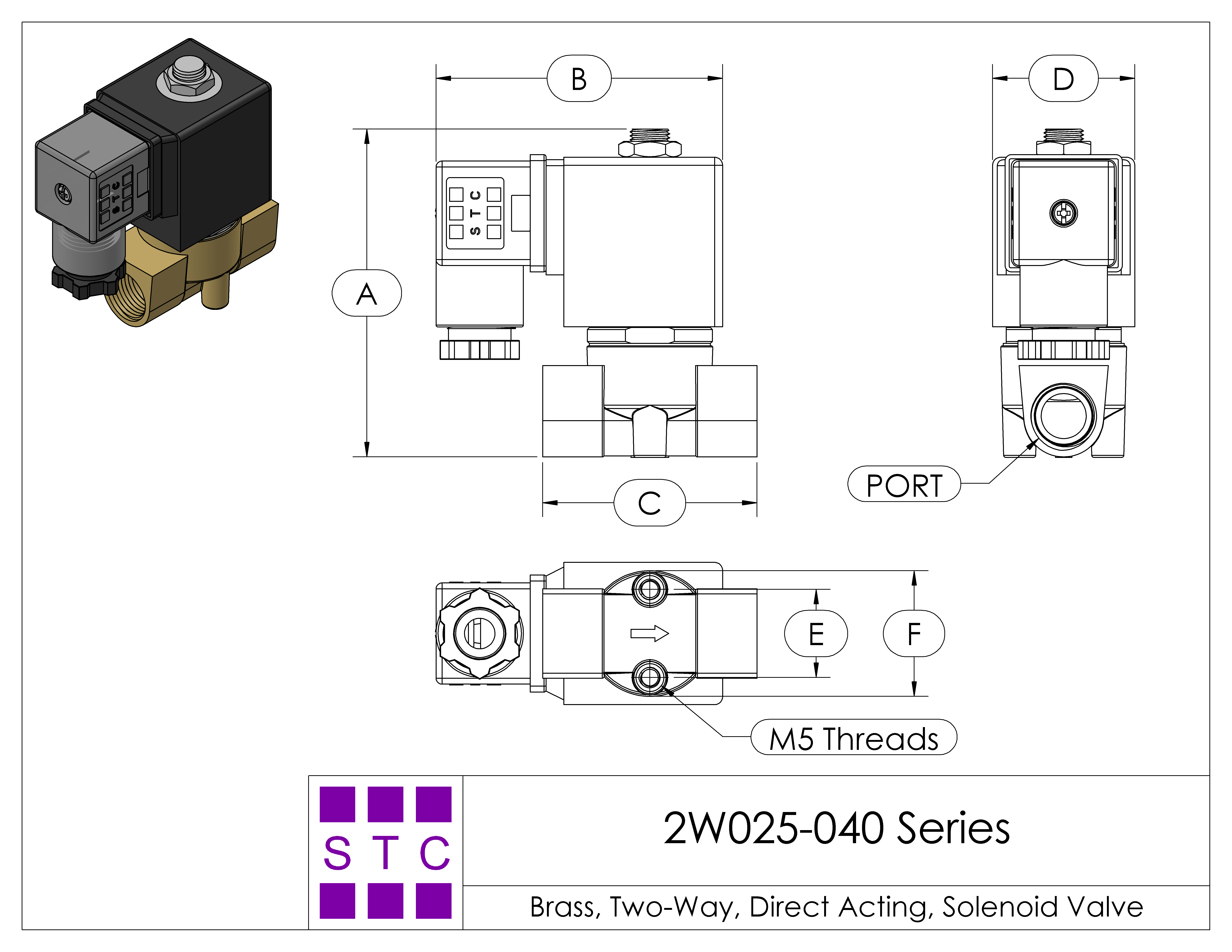
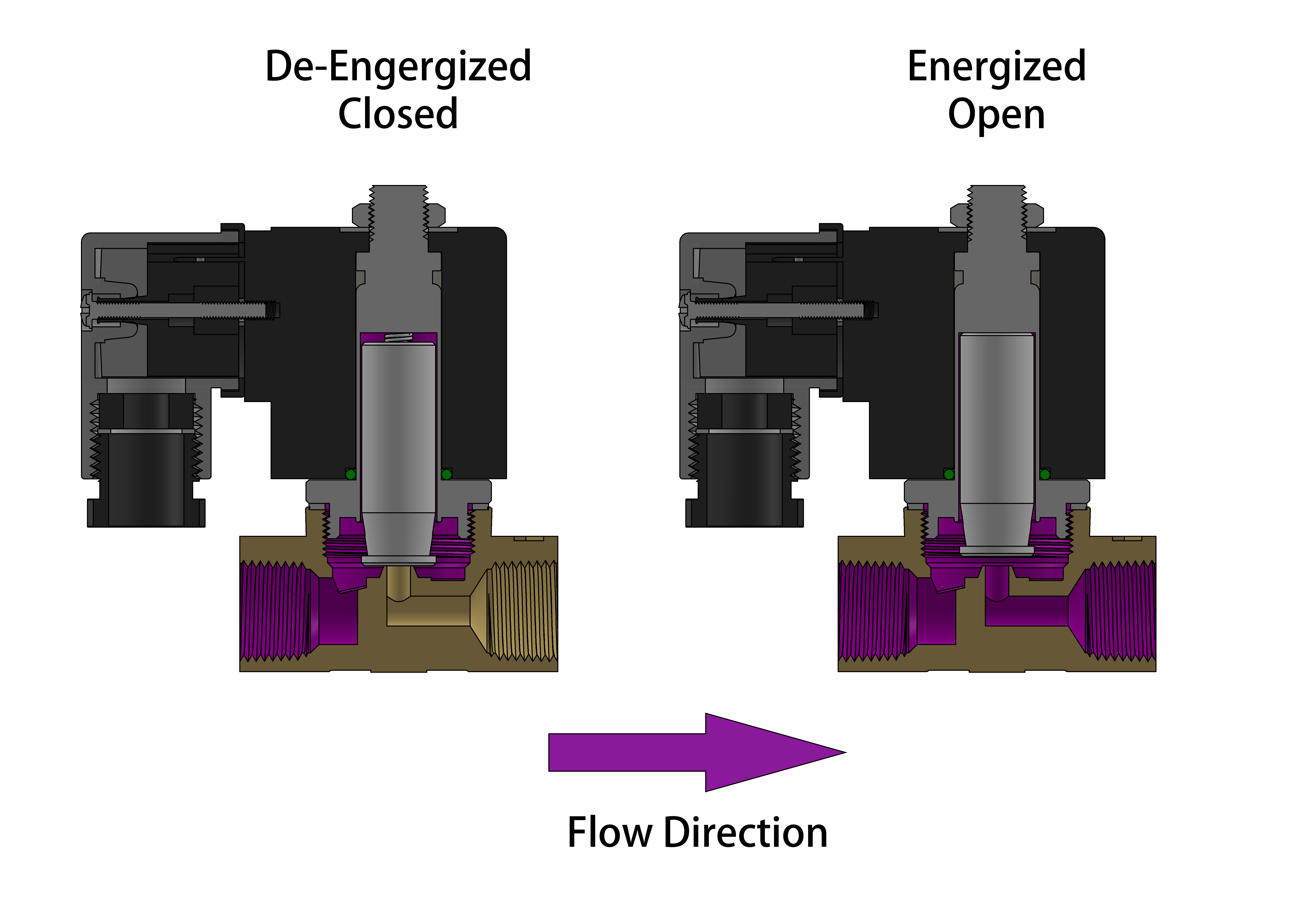
The 2W025-040 valves are direct acting solenoid valves that do not require a minimum
operating differential pressure. As shown in the diagram below, when the coil is de-energized (left diagram),
the plunger rests on the main orifice and is held in place by the plunger spring force, sealing the valve.
When the coil is energized (right diagram), the solenoid lifts the plunger and allows the working medium to
flow through the orifice. The working medium and flow direction are indicated in purple in the diagram.
STC's high performance direct acting plastic body solenoid valves offer reliability, compact and rugged designs, low power consumption, high-speed response, long-life cycle (over 10 million cycles), DIN connections and indicator lights, pre-wired electrical connections, manifold mounting options, and simple installation, maintenance, and control.
ALL standard valves are supplied with Continuous Duty Coils of the proper class of insulation for the service indicated on the valve. It is normal for the coil temperature may become hot after being energized for extended periods. Smoke or burning odor indicates excessive coil temperature and the power should be disconnected to the coil immediately.
SERVICE LIFE: The service life of the solenoid valve depends on the operating conditions such as pressure, temperature, type of medium, and the voltage. Normally the STC solenoid valves are reliable for more than 5 million cycles.
Electrical Coil Connections
STC's high performance direct acting plastic body solenoid valves offer reliability, compact and rugged designs, low power consumption, high-speed response, long-life cycle (over 10 million cycles), DIN connections and indicator lights, pre-wired electrical connections, manifold mounting options, and simple installation, maintenance, and control.
ALL standard valves are supplied with Continuous Duty Coils of the proper class of insulation for the service indicated on the valve. It is normal for the coil temperature may become hot after being energized for extended periods. Smoke or burning odor indicates excessive coil temperature and the power should be disconnected to the coil immediately.
SERVICE LIFE: The service life of the solenoid valve depends on the operating conditions such as pressure, temperature, type of medium, and the voltage. Normally the STC solenoid valves are reliable for more than 5 million cycles.
| Operation Diagram | ||||||
|
- To Connect a DIN Coil:
- Remove the Philips screw from the plastic housting & unplug from the DIN coil.
- Use the removed screw to push the terminal block out of the plastic DIN housing.
- Note the "1", "2", and ground "⏚" symbols.
- For DC DIN Coils, connect "1" to your positive lead and "2" to your negative lead.
- For AC DIN Coils, connect "1" to your HOT lead, "2" to your NEUTRAL lead, and "⏚" to your ground lead, if required.
- To Connect a Grommet Coil:
- For DC Coils, connect the red wire to your positive lead and the black wire to your negative lead.
- For AC Coils, connect the black wire to your HOT lead and the white wire to your NEUTRAL lead.
- For Coils provided with Molded Cables, the color of the wire indicates the type of lead:
- GREEN = Ground Wire
- BLUE = Positive or HOT Wire
- BROWN = Negative or Neutral Wire
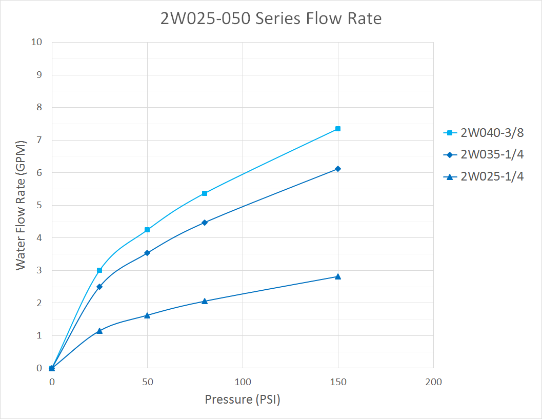
| Flow Rate | ||||||
|
| Home | Terms of Use | Terms of Sale | Career | Contact Us | Click Here to Order |
|
Sizto Tech Corporation © 2001-
. All rights reserved. Last modified: February 11, 2019.
Information contained herein may be changed without prior notification. |
|||||