


Call us at (650) 856-8833 or email us at Sales@StcValve.com.
Solenoid Valve Specifications and Dimensions: 2S160-500 and 2W160-500 Series
|
|
|||||||||||||||||||||||||||||||||||||||||||||||||||||||||||||||||||||||||||||||||||||||||||||||||||||||||||||||||||||||||||||||||||||||||||||||||||||||||||||||||||||||||||||||||||||||||||||||||||||||||||||||||||||||||||||||||||||||||||||||||||||||||||||||||||||||||||||||||||||||||||||||||||||||||||||||||||||||||||||||||||||||||||||||||||||||||||||||||||||||||||||||||||||||||||||||||||||||||
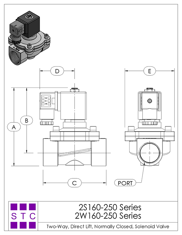
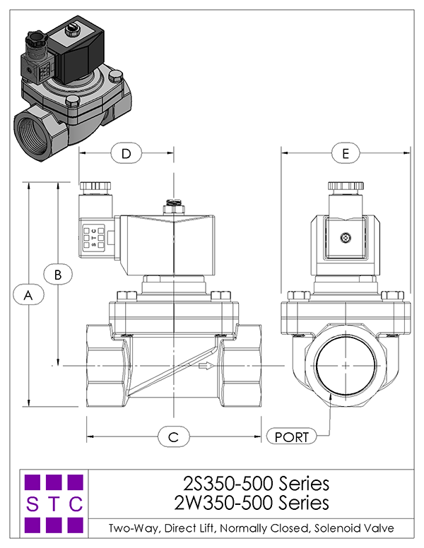
2S & 2W Series 2/2 Direct Lift Diaphragm Normally Closed Solenoid Valve:
This valve is a two-way, normally closed, direct-lift valve and does not require a minimum differential pressure to operate. As shown in the diagrams below, when the coil is de-energized (left diagram), the plunger and flexible diaphragm sit on the main valve orifice. The working medium flows through a tiny "bleed orifice" and pressurizes the cavity above the diaphragm - this system pressure, along with the spring force, seals the valve. When the valve is energized, the diaphragm is pulled away from the main orifice, allowing fluid to flow through the valve. Since the bleed orifice is dimensionally smaller than the main orifice, the system pressure cannot rebuilt on the top of the diaphragm as long as the main orifice remains open. The working medium and flow direction are indicated in purple in the diagrams.
ALL standard valves are supplied with Continuous Duty Coils of the proper class of insulation for the service indicated on the valve. It is normal for the coil temperature may become hot after being energized for extended periods. Smoke or burning odor indicates excessive coil temperature and the power should be disconnected to the coil immediately.
CAUTION: Do not energize the solenoid coil when it is not installed onto the valve. It may cause it to overheat and create a fire hazard.
SERVICE LIFE: The service life of the solenoid valve depends on the operating conditions such as pressure, temperature, type of medium, and the voltage.
- To Connect a DIN Coil:
- Remove the Philips screw from the plastic housting & unplug from the DIN coil.
- Use the removed screw to push the terminal block out of the plastic DIN housing.
- Note the "1", "2", and ground "⏚" symbols.
- For DC DIN Coils, connect "1" to your positive lead and "2" to your negative lead.
- For AC DIN Coils, connect "1" to your HOT lead, "2" to your NEUTRAL lead, and "⏚" to your ground lead, if required.
-
To Connect a Grommet Coil:
- For DC Coils, connect the red wire to your positive lead and the black wire to your negative lead.
- For AC Coils, connect the black wire to your HOT lead and the white wire to your NEUTRAL lead.
- For Coils provided with Molded Cables, the color of the wire indicates the type of lead:
- GREEN = Ground Wire
- BLUE = Positive or HOT Wire
- BROWN = Negative or Neutral Wire

| Home | Terms of Use | Terms of Sale | Career | Contact Us | Click Here to Order |
|
Sizto Tech Corporation © 2001-
. All rights reserved. Sizto Tech Corporation © 2001-2016. All rights reserved. Last modified: October 3, 2018.
Information contained herein may be changed without prior notification. |
|||||