


Call us at (650) 856-8833 or email us at Sales@StcValve.com.
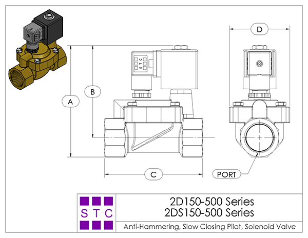
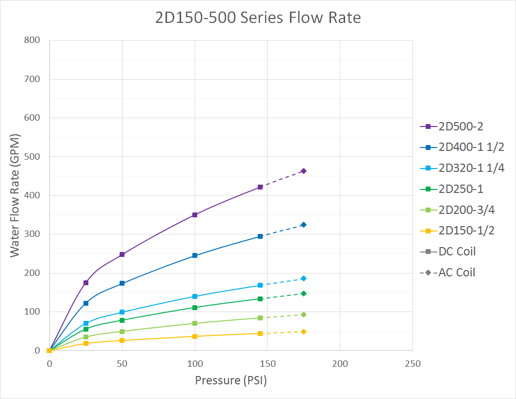
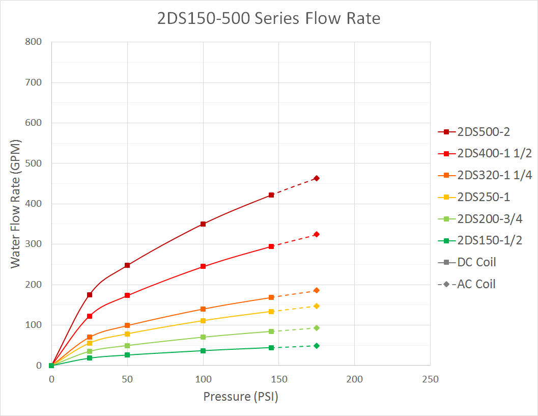
Slow Closing, Anti Water Hammer Solenoid Valve Specifications and Dimensions: 2D150-500 and 2DS150-500 Series
|
|
||||||||||||||||||||||||||||||||||||||||||||||||||||||||||||||||||||||||||||||||||||||||||||||||||||||||||||||||||||||||||||||||||||||||||||||||||||||||||||||||||||||||||||||||||||||||||||||||||||||||||||||||||||||||||||||||||||||||||||||||||||||||||||||||||||||||||||||||||||||||||||||||||||||||||||||||
Installation and Operation:
To connect the valve Inlet and Outlet:
Connect the inlet and outlet in the direction of the arrow marked on the valve.
To install coil:
Put the coil onto the armature tube of the valve. Put the lock-washer and nut onto the armature tube. Hand tighten the nut, then use a wrench to tighten the nut to a quarter turn; do not over-tighten the nut, it may cause the armature tube to fail pre-maturely.
To connect DIN coil:
1. Remove the Philip screw from the plastic housing and unplug it from the DIN coil.
2. From the screw opening, push the terminal block out from the plastic housing.
3. Note the 1, 2 and ground markings on underside of DIN enclosure.
4. For DC DIN Coil, Connect 1 to Positive, 2 to Negative.
5. For AC DIN Coil, connect 1 to HOT wire, 2 to Neutral wire, and if required connect.
6. Do not energize the coil without installing it onto the valve, it will burn the coil and create fire hazards.
Safety Note: Standard valves are supplied with continuous duty coils. The proper class of insulation for the service is indicated on the coil. The coil temperature may become hot after being energized for extended periods, but it is normal. Do not energize the coil without installing it onto the valve or connect the coil to a wrong voltage, as it may overheat and damage the coil; although the coil is made of flame retarded material, misuse of the coil in this manner could create fire hazards and generate smoke or burning odor which indicates excessive coil temperature and should disconnect the power to the coil immediately.
Operation: 2D150-500 Series 2/2 Pilot Operated Diaphragm Solenoid Valve NC
To open: when the valve receives an electrical signal, a magnetic field is formed which attracts the plunger covering the pilot orifice to lift off, causing system pressure (holding the diaphragm/piston closed) to drop. As system pressure on the top of the diaphragm/piston is reduced, full system pressure on the other side of the diaphragm/piston acts to lift the diaphragm/piston away from the main orifice, which allows media flow through the valve. Since the bleed orifice is dimensionally smaller than the pilot orifice, the system pressure can t rebuild on the top of the diaphragm/piston as long as the pilot orifice remains open.
To close: when the valve is de-energized, it releases its hold on the plunger. Then the plunger drops and covers the main orifice. The system pressure builds up on the top of the diaphragm/piston through the bleed orifice, forcing the diaphragm/piston down until it covers the main orifice and stops media flow through the valve.
| Home | Terms of Use | Terms of Sale | Career | Contact Us | Click Here to Order |
|
Sizto Tech Corporation © 2001-
. All rights reserved. Last modified: December 5, 2018.
Information contained herein may be changed without prior notification. |
|||||