Call us at (650) 856-8833 or email us at Sales@StcValve.com.
Quick Exhaust Air Valve & Shuttle Air Valve Dimensions
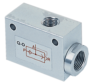
Quick Exhaust Air Valve Operation:
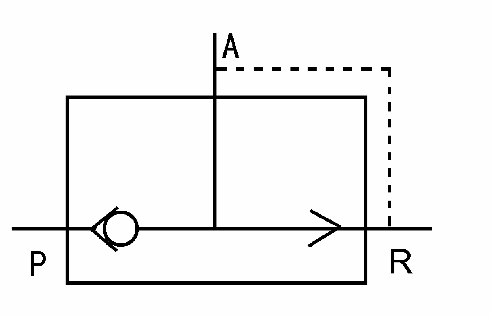
As shown in the pneumatic symbol below, the Quick Exhaust Valve has three connecting ports: a pressure port (P) & an exhaust port (R) on opposite ends of the valve, and an outlet port (A) on the top of the valve. When air pressure is applied to the pressure port (P), an internal check valve piston allows air to move from the pressure port (P) to the outlet port (A). When the air pressure is removed from the pressure port (P), the internal check valve piston allows air to exhaust from the outlet port (A) to the exhaust port (R). The Quick Exhaust Air Valve is designed to allow air to be quickly exhausted from an air reservoir or an air cylinder to achieve higher cycle speeds.
|

|
|||||||||
Quick Exhaust Valve (Units in mm) |
||||||||||
| Part No. | Bore (NPT) | G (NPT) | L | W | H | A | B | C | D | Cv |
| QE N1/8 | 1/4" | 1/8" | 46 | 20 | 32 | 30 | 4.3 | 27 | 40 | 1 |
| QE N1/4 | 3/8" | 1/4" | 62 | 25 | 40 | 39 | 5.6 | 33.5 | 55 | 1.3 |
| QE N3/8 | 3/8" | 3/8" | 62 | 25 | 40 | 39 | 5.6 | 33.5 | 55 | 1.4 |
| QE N1/2 | 3/8" | 1/2" | 98 | 38 | 64 | 60 | 8.5 | 51 | 90 | 4 |
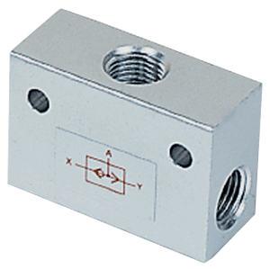
Shuttle Air Valve Operation:
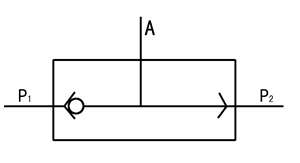
As shown in the pneumatic symbol below, the Shuttle Air Valve has three connecting ports: two pressure ports (P1 & P2), one on each end of the valve, and an outlet port (A) on the top of the valve. An internal check valve piston moves freely between the two ends of the valve. When air pressure is applied to one of the pressure ports (e.g., P1), it pushes the piston towards the opposite end of the valve. This prevents the air from exiting through the opposite pressure port (e.g., P2), but allows air to flow through the outlet port (A). The Shuttle Air Valve is designed to allow two different air pressure sources (P1 & P2) to be alternately shuttled to a single outlet (A), while preventing backflow from one pressure source to the other.
|
|
|||||||
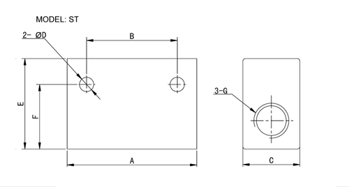
Shuttle Valve (Units in mm) |
||||||||
| Part No. | G (NPT) | A | B | C | D | E | F | Cv |
| ST N1/8 | 1/8 | 40 | 24 | 16 | 4.5 | 25 | 21 | 0.35 |
| ST N1/4 | 1/4 | 50 | 35 | 22 | 5.5 | 35 | 25 | 1 |
| ST N3/8 | 3/8 | 75 | 48 | 30 | 7 | 50 | 42 | 2 |
| ST N1/2 | 1/2 | 75 | 48 | 30 | 7 | 50 | 42 | 3.5 |
| ST N3/4 | 3/4 | 110 | 72 | 40 | 7 | 70 | 58 | 6 |
| ST N1 | 1 | 110 | 72 | 40 | 7 | 70 | 58 | 10 |
| Home | Terms of Use | Terms of Sale | Career | Contact Us | Click Here to Order |
|
Sizto Tech Corporation © 2001-. All rights reserved. Last modified:June 20, 2022.
Information contained herein may be changed without prior notification. |
|||||


