|
Solenoid Valve
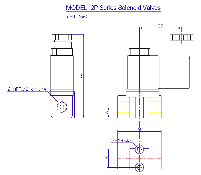
Specifications & Dimensions:
2P Series
|
Part No. |
Unit Price |
Valve Picture |
Port Size
(NPT) |
Voltage Options |
Electrical Entry Options |
Port No/ Position/Solenoid |
Cv
Flow Rate |
Response Time |
Power Consumption
|
|
| 2P025
1/8 |
$21.23 |
 |
1/8 NPT |
1=12VDC
2=24VDC
2A=24VAC
3=110VAC
4=220VAC
(50/60Hz) |
G=Grommet
D= DIN (with LED indicator) |
2/2/1
Direct Acting
Normally closed
Two Way Valve |
0.23
22 SCFM @100 PSI
|
< 20 ms |
3W for 60PSI
4.8W for 115 PSI
6.5W for 150 PSI |
 |
| 2P025
1/4 |
1/4 NPT |
| 2P035
1/8 |
1/8 NPT |
1=12VDC
2=24VDC
2A=24VAC
3=110VAC
4=220VAC
(50/60Hz) |
G=Grommet
D= DIN (with LED indicator) |
3/2/1
Direct Acting
Normally closed
Three Way Valve |
0.1
5 SCFM @100 PSI |
< 20 ms |
3W for 60PSI
4.8W for 115 PSI
6.5W for 150 PSI |
 |
| 2P035
1/4 |
1/4 NPT |
|
2P Series Valve
Specifications |
|
Port & Mounting |
Body Ported |
|
Action & Motion |
Direct Acting, Normally Closed, Two Position, 2 to 3 Way |
|
Operating Pressure |
28" Hg to 115 PSI (Coil Wattage Dependent) |
|
Working
Medium |
air, inert gas & liquid |
|
Maximum Pressure |
150 PSI |
|
Operating Temperature |
(-5 to 80 Deg. C) with non-freezing medium |
|
Coil Insulation & Protection Class |
F Class, IP65 (CE Certification) |
|
Coil Duty
Cycle |
100% ED |
|
Electrical Connection |
D = DIN (with LED indicator, conduit terminal)
G = Grommet (12” Lead Wire) |
|
Body Material |
Engineered Plastic |
|
Seal Material |
NBR (Buna N) |
|
Armature Tube |
Brass |
|
Plunger & Spring |
Stainless steel |
|
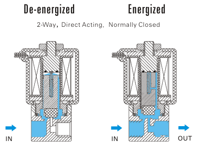
2P Series Valves are DIRECT
ACTING solenoid valves and do not require a minimum operating differential
pressure. As shown below when the coil is energized (right diagram), it lifts the solenoid plunger, which
normally rests on the valve seat and lifts it to open the main
valve orifice. When the coil is de-energized (right
diagram), the spring force the
plunger return to the valve seat to close the valve orifice.
 |
|
Electrical Coil Connections |
|
For DIN Coil |
To connect DIN coil:
1. Remove the Philip screw from the plastic housing and unplug it from
the DIN coil.
2. From the screw opening, use the screw to push the terminal block out
of the
plastic housing.
3. Note the 1, 2 and ground markings on
underside of DIN enclosure.
4. For DC DIN Coil, Connect 1 to Positive, 2 to Negative.
5. For AC DIN Coil, connect 1 to HOT wire, 2 to Neutral
wire, and if required connect ground to ground wire.
|
|
For Grommet Coil
|
To connect Grommet coil:
1. For DC Coil, connect one of the two wires to Positive, and
the other wire to
Negative.
2. For AC Coil, connect one of the two wires to HOT wire, and the
other wire to neutral
wire. |
|
CAUTION: Do not energize the solenoid coil when
it is not installed onto the valve. It may cause it to overheat and create a
fire hazard. |
|
STC's high performance
direct acting plastic body solenoid valves offer reliability, compact
and rugged designs, low power consumption, high-speed response,
long life cycle - over 10 million cycles, DIN connections and
indicator lights, pre-wired electric connections, manifold mounting
options, and simple installation,
maintenance, and control. |
 |
|


